 |
Wondering Right Here! |
A Fun Old Porcelain Sign and Ancient Tools
|
Meet the MasterTech!
|
If your Mfgr. says: That motor's 7 years old!!
Part is no longer available. We lose $$ on service! EPA made me do it! Part's at central warehouse, you'll get it next month. We don't make parts for those. We only do warranty work. Our techs only fix late models. No clue what's wrong! So we'll work time & material. Baloney!! Contact
|
|

|
|||||||||||||||||||||||||||||||||||||||||||||||||||||||||
OMC 60 DEGREE V6 OPTICAL IGNITION TIPS
A
guide to troubleshooting the Johnson/Evinrude The following information is presented for the use of MASTERTECH'S customers as a courtesy by CDI Electronics. This ignition system produces very high voltages and due care and caution must be practiced in working with it. The timing wheel cover is a machinery guard. Use care and caution when working on a running engine. MASTERTECH MARINE, CDI Electronics and their respective employees cannot be held responsible for any injuries or damage resulting from the use of, or application of the following data. Please read the final paragraph below. We have chosen to narrow this troubleshooting guide to the Johnson/Evinrude 60° 6-cylinder ignition (OIS 2000) 1991-2003 model years. Due to the differences in this ignition system, troubleshooting can be somewhat difficult if you are not familiar with the design. The other Johnson/Evinrude QuikStart ignitions use stator charge coils and a power coil to provide high voltage and power for the QuikStart and rev limiter circuits. They require a timer base for triggering and use separate magnets for the high voltage and triggering the timer base. The OIS 2000 optical system uses the stator charge coils to provide high voltage for the firing of the ignition coils and a power coil to provide power for the electronics both inside the power pack and inside the sensor. The other QuickStart models will run the engine without the power coil being connected (of course this will burn out the control circuits inside the power pack). The OIS 2000 ignition has to have the power coil supplying power in order to operate the QuickStart, S.L.O.W., rev limiter, and fire the coils beyond cranking speed. The optical sensor located on the top is fed power from the power pack and sends crankshaft position, cylinder location and direction of rotation back to the power pack. The pack is smart enough to know not to fire if the engine is not turning in the right direction. S.L.O.W. functions to reduce the engine RPM to approximately 2,500 when the engine overheats. QuikStart (a 10° timing advance) activates as long as the engine RPM is below 1,100, the engine temperature is below 105 F and the yellow/red wire from the starter solenoid is not feeding 12 volts DC to the power pack all of the time. QuikStart also will activate for five to 10 seconds each time the engine is started regardless of engine temperature. At cranking speed the voltage from the stator may not be enough to operate the circuits inside the power pack, therefore there is battery voltage supplied from the starter solenoid via the yellow/red striped wire. The extra voltage is needed in order for the optical sensor to operate correctly as low voltage from the battery and/or stator can cause intermittent or no fire at all. There are a couple of critical items you need to be aware of on these engines. First, the spark plug wires need to be the gray inductive resistor wires - these are not automotive wires. Secondly, the spark plugs should be the factory recommended QL78YC. Use of other spark plugs or wires can cause problems inside the power pack from RFI and MFI noise. CDI Electronics has the spark plug wires available as a set P/N: 931-4921. A breakthrough at CDI Electronics has allowed the use of microprocessor digital control circuits to handle the timing, QuikStart, S.L.O.W., rev limiter and data logging inside the power pack. This allows the timing to be set using a timing light, remote starter, spark gap tester, piston stop tool and a jumper wire. With these new digital power packs, you disconnect the port temperature switch/sensor leads and use a jumper wire to short the tan temperature sensor wire to engine ground. Once you have verified the timing pointer using a piston stop tool (or a dial indicator), connect all spark plug wires to a spark gap tester, and connect a remote starter to the engine and a timing light to the No.1 spark plug wire. When you crank the engine over with the remote starter and check the timing, you will notice the timing is set to approximately 4°- 6° ATDC (after top dead center). By advancing the throttle all the way and rechecking the timing for WOT (wide open throttle), you should see approximately 19° - 20° BTDC (before top dead center). Without this timing feature built into the power pack, you would not be able to easily set the timing for idle or WOT without the Johnson/Evinrude optical diagnostic tool. Another nice features allowed by the digital circuitry include the ability to compensate for a bad temperature switch, a smoother rev limit, customized rev limiters and special timing curves. Additional items to be aware of:
Originally the spark plugs were the QL82YC, but that recommendation was changed to the QL78YC for improved performance. Helpful tools used by the author in troubleshooting these engines: No fire at all
Low readings on all checks indicate a possible problem with the flywheel magnets that needs to be checked. Service note:It is recommended that liquid neoprene be applied to the areas where piercing probes were used.
Note: If the DVA values are below these specifications, the power pack or sensor is likely bad.
 No spark on one bank of cylinders
 Note: If the power pack has no spark on one bank and the readings are good, replace the power pack.
Note:
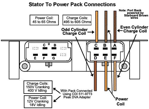
Will not rev up Engine will not rev up above idle speed or only has spark as long as the starter solenoid is engaged: Using piercing probes and DVA adapter or DVA Multimeter, check the DVA voltage while connected as follows:
Note: Engine will not rev up above 2500 RPM and shakes hard (S.L.O.W. activated):
Check the yellow/red wire for 12 volts while the engine is running. You should only see voltage on this wire while the starter solenoid is engaged. As you can see, there are several critical steps involved with the troubleshooting of outboard ignition systems. The electronic components are not "magic black boxes" mysteriously making spark appear, but rather a complex system giving the engine the correct voltages at the correct time for years of trouble-free boating. Additional information for other engines can be obtained by visiting www.am-tech.org or www.rapair.com. I would like to give a special thanks to the technical service personnel at CDI Electronics for their help with this article. Author Clark Beard is a senior technical service advisor for CDI Electronics and also serves on the advisory board of AMTECH. IF you wish to service or repair your own ignition system, I HIGHLY RECOMMEND you obtain an OEM model-specific service manual to help you. We have most available Right Here at Mastertech. |
|||||||||||||||||||||||||||||||||||||||||||||||||||||||||
 |
Please review our Warranty, Returns & Refunds policies before you place an order. DISCLAIMER The information provided on these pages is correct to the best of my knowledge, however the MasterTech makes no warranty, express or implied, regarding the use of, results of, or liability created from, application of this data. This information is disseminated in good faith, however MasterTech assumes NO LIABILITY whatsoever in regard to this service. The information, software, products, and services published on this web site may include inaccuracies or typographical errors. Changes are periodically added to the information herein. Mastertech may make improvements to this site at any time. Parts ordered from this website may or may not be in dealer stock at the time of order. Thank you for reading. Revised
|
||||||||||||||||||||||||||||||||||||||||||||||||||||||||